| |
| |||||||
| View Poll Results: Would you be interested in this kind of chassis? | |||
| Yes | | 9 | 45.00% |
| No | | 11 | 55.00% |
| Voters: 20. You may not vote on this poll | |||
 |
| | LinkBack | Thread Tools | Display Modes |
 01-13-2011, 07:16 PM
| #121 |
| RCC Addict  Join Date: Mar 2010 Location: Colorado Springs, Co
Posts: 1,441
|
Now that theres a few MVP's out there post up any final changes or additions you would like to see. Also Im working on a set up sheet you can d-load for tuning. |

|  |
| Sponsored Links | |
| | |
|
01-14-2011, 10:28 AM
| #122 |
| Pebble Pounder Join Date: Jan 2009 Location: upstate
Posts: 111
|
Very interesting chassis and nice write up toying with the idea of getting another mrc and this chassis is rockin'
|
|
| |
|
01-14-2011, 09:39 PM
| #123 |
| RCC Addict Join Date: Mar 2010 Location: Colorado Springs, Co
Posts: 1,441
|
Finaly got the BEC instaled, wow what a difference. Now i just need the snow to go away so i can do some testing... Ive been waiting for ever to get this thing on the rocks!!!!
|
|
| |
|
01-15-2011, 07:10 AM
| #124 | |
| I wanna be Dave Join Date: May 2010 Location: The east coast
Posts: 2,599
| Quote:
| |
|
| |
|
01-15-2011, 08:58 AM
| #125 |
| RCC Addict Join Date: Mar 2010 Location: Colorado Springs, Co
Posts: 1,441
|
The problem i was having was that when I get bound up the stearing quit or I could stear and there was no throtle that and the servo was really slugish. It worked fine for a while but once I updated the sidewinder and set up the crawler specific settings it started giving me issues. Now with the BEC, I'm golden. I dont think the sidewinder has a BEC built in to it so this definantly helps. I'me running a Losi Slider motor at the moment which works awesome but I just ordered a Holms 33T so hopefuly get a little more tourque as the slider still at times won't have the hill hold I would like to have. |
|
| |
|
01-15-2011, 10:04 AM
| #126 |
| Quarry Creeper Join Date: Sep 2010 Location: Dewsbury, UK
Posts: 250
|
Holmes' 33T mini is great. fantastic torque/speed/drag brake. I am sure you will love it!
|
|
| |
|
01-15-2011, 11:32 AM
| #127 |
| RCC Addict Join Date: Mar 2010 Location: Colorado Springs, Co
Posts: 1,441
|
Here's some picture I took to show how I cramed all my eletronics into the MVP Chassis. This is what's in there. 1/18 CC Sidewinder LOSI Spektrum Reciever CC BEC 10A - Wired to the servo. I did all the wiring on the center piece while it's out of the truck to make life easier. Once you have everything mounted and secured to the center piece of the truck, insert it and you'll save you're self alot of frustration. Starting - Sidewinder in the nose of the Rig   The RX in the tail Plate   The BEC on the Passengers Outside of the plates   The Swich and the Battery connecter  Changes for - v3 Some if the changes I've desided on will save weight and give it a cleaner side to keep things from hanging up. If you notice in this picture I'm using flat counter sunk hex's for the lower mouns in the front and for the upper link mounts on the chassis side. This will save on weight and allow easier fitting of the body panle. Also I'm suplying 2mm hardware that is countersunk into the chassis for mounting the Skid to prevent hangups on the outer side of the skid. I will also be working on trimming out some of the material on the chassis in key location to save weight as well. |
|
| |
|
01-15-2011, 01:44 PM
| #128 |
| Pebble Pounder Join Date: Aug 2010 Location: The Divide
Posts: 104
|  on the countersunk heads, nice thinking. Trimmed some of my chassis and with the removed spacers I've dropped the weight from 85g to a hair less than 70g, but it changed the look of the chassis (a little). I don't want to start hijacking your thread, so let me know if you want some pics posted. on the countersunk heads, nice thinking. Trimmed some of my chassis and with the removed spacers I've dropped the weight from 85g to a hair less than 70g, but it changed the look of the chassis (a little). I don't want to start hijacking your thread, so let me know if you want some pics posted.
|
|
| |
|
01-15-2011, 05:39 PM
| #129 | |
| RCC Addict Join Date: Mar 2010 Location: Colorado Springs, Co
Posts: 1,441
| Quote:
| |
|
| |
|
01-15-2011, 07:28 PM
| #130 |
| Pebble Pounder Join Date: Aug 2010 Location: The Divide
Posts: 104
|
Out of the package, mocked up/screws finger tight, had a rear weight bias. Not a major amount of weight, but set on a flat surface the chassis would fall back.  Just removing some hardware from the back end balanced it out.  Trimmed off rear and nose of the shock plates, and part off the window.  Removed more braces and spacers. Dropped the weight from 85g to 70g.  Set the chassis on its side with approx. 5 lbs. on top, no flexing or cracking, definitely held the weight. Your chassis is solid, I really can not wait to assemble and run this rig. Thanks Again. Last edited by WTF; 01-17-2011 at 02:40 AM. |
|
| |
|
01-16-2011, 07:50 AM
| #131 |
| RCC Addict Join Date: Mar 2010 Location: Colorado Springs, Co
Posts: 1,441
|
First thing is the conctruction and painting of the body panels. You will need: .030 Lexan or other material Exacto knife Paint Tape Patience(I lack this one) Cut your paper template out and hold it up the the chassis and validate that it's the corect size. If you need another template contact me and I will e-mail you another template. Next tape down all edges to your desired material. Make sure you peal the backing off the lexan sheet before you paint. If you wish to mask designs into the paint you can use tape or liquid mask to do so. This is why we tape the templates to the lexan prior to paint. It enables you to mask your pannel corectly so the end result looks correct.    Paint your panels... Make sure they are completly dry before you attempt so cut them out. IMPORTANT!!!! - Before you cut your template out, use an exacto knife to poke a small hole in the lexan in the center of the guide to help you find it later when it comes time to make the holes. Don't make it too noticable incase when you cut the lexan you have to move the hole location slightly.    Once the panel is cut, peal off the protective film and drill or spin your exacto knife on the marked spot to make a hole just big enought for a zip strip or 3mm screw.   Side panels tend to be a little more tricky to get them to lay flat once instaled. Hold off on makeing the mounting holes until you are ready to put this pannle on. Do and mount 1 hole at a time to make sure they are properly ligned up. Start by removing two screws on top that will hole the top of the panel in place. You should look like this.  Start by holding the panel up to the chassis and checking your initial marks. if they are good make of the top holes and mount it to the chassis. Once that is done mark and make the rear top hole and mount it to the chassis. You should look like the middle picture now. With the pannel mounted lift the edge and see where the hole is and poke your exacto knife thought and spin it gently till the hole is the corext size. Mount the screw then to the last hole.    for the full length hod and tail piece, take a lighter and gently heat where you want to bend the pannel to fit the inside contoure. If done corectly, you will only need one zip tie in the front and one in the rear. Is might be easier to form the full lenght pannel with the roof off.   Once it's all ziped in place you'll have your finished product. Enjoy.    |
|
| |
|
01-17-2011, 09:18 PM
| #132 |
| RCC Addict Join Date: Mar 2010 Location: Colorado Springs, Co
Posts: 1,441
|
Well, I've been saving up my pennies for my entry fee into Morotama. I'm hopping that Motorama will be this lil puppies debuet. I just wish the snow would go away so I can get out on the rox with it just a bit before Motorama hits off... I think the only thing left that I need to do is really tune in the stearing. The nuckles and swing shafts are capable of a much tighter turning radious then I'm getting out of them. Short of buying a OTA kit from RC bors I'm not sure what else to do at this point. Look at these photos, you can see the the outer wheel is turned sharper than the inner wheel for some reason???? I've tried adjusting the length of the drag link but it didn't seam to help in the least.   Here's a front on view that should give you a good Idea of how I set mine up.  Any thoughts or sugestions would be awesome. |
|
| |
|
01-18-2011, 04:20 AM
| #133 | |
| I wanna be Dave Join Date: May 2010 Location: The east coast
Posts: 2,599
| Quote:
adam, i'm no expert on this but is the fact the knuckles are not zero ackerman giving the different angles when you turn? if the drag link mounting point was directly in front of the knuckle pivot point (versus inside, i.e. closer to the centerline of the axle) it would maintain constant steering angles left and right. basically the distance between the knuckle pivot points is longer than the draglink with your current setup. i'm looking at the same issue on my maxstone 16 which is why i've been trying to read up on it myself. | |
|
| |
|
01-18-2011, 06:37 AM
| #134 |
| RCC Addict Join Date: Mar 2010 Location: Colorado Springs, Co
Posts: 1,441
|
Thanks on pointing me in the corect direction to find an answer. Here's what I found. You can find the whole article here - http://www.rctek.com/technical/handl...principle.html Ackerman Steering Principle The Ackerman Steering Principle defines the geometry that is applied to all vehicles (two or four wheel drive) to enable the correct turning angle of the steering wheels to be generated when negotiating a corner or a curve. Before this principle was developed the vehicles of the time (horse drawn) were fitted with parallel steering arms and suffered from poor steering performance. A Mr Rudolf Ackerman is credited with working out that using angled steering arms would cure these vehicles of such steering problems. Why & How? The animation on the right depicts a car travelling around a corner (in this case, a continous one!). The red lines represent the path that the wheels follow. If you Play it you will notice that the inside wheels of the car are following a smaller diameter circle than the outside wheels. If both the wheels were turned by the same amount, the inside wheel would scrub (effectively sliding sideways) and lessen the effectiveness of the steering. This tyre scrubbing, which also creates unwanted heat and wear in the tyre, can be eliminated by turning the inside wheel at a greater angle than the outside one. You may Stop the animation if required.  The difference in the angles of the inside and outside wheels may be better understood by studying the diagram to the right, where we have marked the inside and outside radius that each of the tyres passes through. The Inside Radius (Ri) and the Outside Radius (Ro) are dependant on a number of factors including the car width and the tightness of the corner the car is intended to pass through. Measurements for angles of the arms are therefore not derived from these lines, they are derived from the distances shown in More, Less & True Ackerman Steering section below. Aligning both wheels in the proper direction of travel creates consistent steering without undue wear and heat being generated in either of the tyres. Obviously with turning one wheel more than the other you are mis-aligning the wheels and you need to do this whilst allowing both wheels to be pointing straight forward when the car is not turning. To enable this to happen, the mis-alignment needs to progress from zero (wheels pointing straight ahead) to a point where there is a sufficiently different angle between both wheels to create the alignment of both wheels when they are both fully turned. Steering Arm Angles Creating mis-alignment of the wheels is, as mentioned in the introduction, achieved by a combination of the angle and the length of the steering arms. Below we have a few diagrams that give examples using parallel and angled steering arms to demonstrate why there is a need for using the Ackerman Steering Principle. Please ignore the size difference of the yellow circles in the diagrams below. They are a result of the way the steering arms were drawn for simplicity and are not meant to add confusion to the description of the Ackerman Principle we are describing in this article. Parallel Steering Arms  The steering arms in the diagram to the left are straight and parallel to the sides of the vehicle, which would create a situation where equal movement of the steering servo would produce equal angular movement of the wheels. Why this equal angular movement occurs can be seen by studying the animation of a wheel to the right, where a red circle has been drawn to show how the sideways movement of the steering arms is converted in a circular one. As the steering arm pivot point (A) is vertically aligned with the king pin pivot point (B) when the wheel is pointing straight ahead, the same amount of movement to the Left or to the Right moves the steering arm pivot point the same vertical distance forward of it's starting point. You can reset the animation to its Starting position if required. A more complete explanation of the issues involved is available in our The Circle article. If this steering geometry was applied to a remote controlled model car, then either or both of the front wheels would not be at the correct steering angle and would result in unpredictable steering. Angled Steering Arms  The steering arms in the image to the left are angled inwards to create a means for the wheel angles to change at a different rate. This is the basis of the Ackerman Steering Principle and creates this unequal angular movement of the wheels. Why this unequal angular movement occurs is shown in the animated image to the right and happens because of the relative position of the steering arm pivot point (A) around the circumference of the red circle that has been drawn in to show how the steering arm pivot point moves around the king pin pivot point (B). As the steering arms are angled, the pivot point (A) is not vertically aligned and is, in a straight ahead position, part way round the circle. Because of this, a Right movement of the steering arm will cause the pivot point to move a greater distance in the forward direction than a Left movement of the steering arm. You can reset the animation to its Starting position if required. A more complete explanation of the issues involved is available in our The Circle article.  An important point worth noting is that this unequal angular movement is exponential, that is, the more you turn the wheel the greater the angular difference between the wheels - otherwise both the wheels would never point forward when the car is not turning. The deliberately emphasised example above would result in a wheel angle difference somewhere in the region of the figures given in the image to the left, whereas the parallel steering arm example would have resulted in the same wheel angles being generated on each side. --------------------------------------------------------------------- These are often heard terms in model car racing and refer to the amount of inequality of the angles of the wheels relative to true Ackerman steering geometry. True Ackerman Angle - Zero Toe On Turn In   True Ackerman steering geometry is shown in the image to the right. This is defined by angling the steering arms so that a line drawn between both the king pin and steering arm pivot points intersects with the centre line of the rear axle. As this gives true Ackerman steering geometry, there is no Toe Angle change on the inside wheel (the wheel is aligned with the circumference of the circle), which can be seen in the image above left. More Ackerman Angle - Toe Out On Turn In   More Ackerman angle can be added to a steering set-up, which involves adjusting the angle of the pivot points on the steering arms so that the point of intersection is forward of the centre line of the rear axle. Please refer to the image on the right. This steering geometry achieves greater angular inequality of the turned wheels, which results in the inside wheel trying to follow a smaller diameter circle than it actually does. This effect can be seen in the image above left and generates Toe Out on the front inside wheel. Less Ackerman Angle - Toe In On Turn In   Less Ackerman angle can be set on a steering set-up, which involves adjusting the angle of the pivot points on the steering arms so that the point of intersection is behind the centre line of the rear axle. Please refer to the image on the right. This steering geometry achieves a reduced amount of angular inequality of the turned wheels, which results in the inside wheel trying to follow a larger diameter circle than it actually does. This effect can be seen in the image above left and generates Toe In on the front inside wheel. |
|
| |
|
01-18-2011, 06:45 AM
| #135 |
| RCC Addict Join Date: Mar 2010 Location: Colorado Springs, Co
Posts: 1,441
|
So if I'm understanding this corectly, then I sould drill and tap this location right behind the pivit point on my stearing arm?
|
|
| |
|
01-18-2011, 07:41 AM
| #136 |
| I wanna be Dave Join Date: May 2010 Location: Stowe
Posts: 3,987
|
Yes Adam you are correct. drill and tap where you have your dot, cut off the rest. If you look at the EGRESSor knuckles I have, the spot to mount the draglink is inline with the king pin. This will give you tighter steering. The only limitation will be the CVD. I love these knuckles. I will be ordering one of your MVP chassis for my son for next season.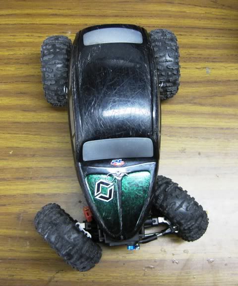 |
|
| |
|
01-18-2011, 08:28 AM
| #137 |
| Quarry Creeper Join Date: Sep 2010 Location: Dewsbury, UK
Posts: 250
|
Deffo go for zero ackerman. It will improve turning abilty for two reasons, the wheels will turn together, (your inside wheel should then turn more than it does now = better steering) and the tires will now be nearer to working together (i.e. they are not fighting against each other - results in less tire scrub and therefor a tighter turning circle.). [In a perfect world we would be trying to achieve better than zero ackerman, so the inner wheel turns more than the outer wheel (then they both follow their respective circles, less fighting more turning, but not great to do on the MRC due to lack of material and poor leverage on the steering) Since stock geometry, my MRC now has a turning cicle about half what it was (give or take). Remember when drilling: 2.5mm drill, 3mm tap. And chop off the excess arm once done and happy - it gets in the way. Losi CVDs will further improve the steering angles (limits) a few degrees. p.s. Nice rig, looks awesome. Great panels too! Last edited by Gfresh; 01-18-2011 at 08:30 AM. |
|
| |
|
01-18-2011, 09:30 PM
| #138 |
| RCC Addict Join Date: Mar 2010 Location: Colorado Springs, Co
Posts: 1,441
|
I got the Ackerman set properly and now I get a nice tight turining radious. Thanks guies for pointing me in the right direction... now the only problem is that my servo seams to be finaly checking out... looks like a new servo is in my near future.      |
|
| |
|
01-19-2011, 03:35 AM
| #139 |
| Quarry Creeper Join Date: Sep 2010 Location: Dewsbury, UK
Posts: 250
|
Looking good! Your servo will be working harder now, as the zero ackerman drilling gives less leverage over the tires. I got round this by using my short arm servo horn (hole to hole its about 12mm, maybe 13mm) - this gives loads more torque (shorter servo arm in my case gives about 40% more torque. Just think for example: 100oz.inch servo at 1/2 inch = 200oz.). About 12mm is the shortest I can get away with and still hit full lock to lock. G |
|
| |
|
01-19-2011, 04:16 AM
| #140 |
| I wanna be Dave Join Date: May 2010 Location: The east coast
Posts: 2,599
|
this looks like a mod i need to do on my maxstone 16. adam, i'm glad it has worked out so well for you.
|
|
| |
|
| |


 Linear Mode


